The developed coursework during the delivery of Power Electronics Module has been designed to improve the students experience dealing with information and knowledge at the component level and system level.
Part A in the coursework is an assessment of 3-4 power switches varies from Si MOSFET, Si IGBT to SiC MOSFET. The assessment includes the switching and conduction losses.
Part B in the coursework is to design a closed-loop buck converter using LTSpice. Manufacturing one will be beyond the project duration.
Therefore, for the practical part of the CW, Part A, a Single Switch Experimental Kit is proposed and designed. The kit can serve for any converter that uses one power switch like, asynchronous buck, boost, buck-boost and other converters.
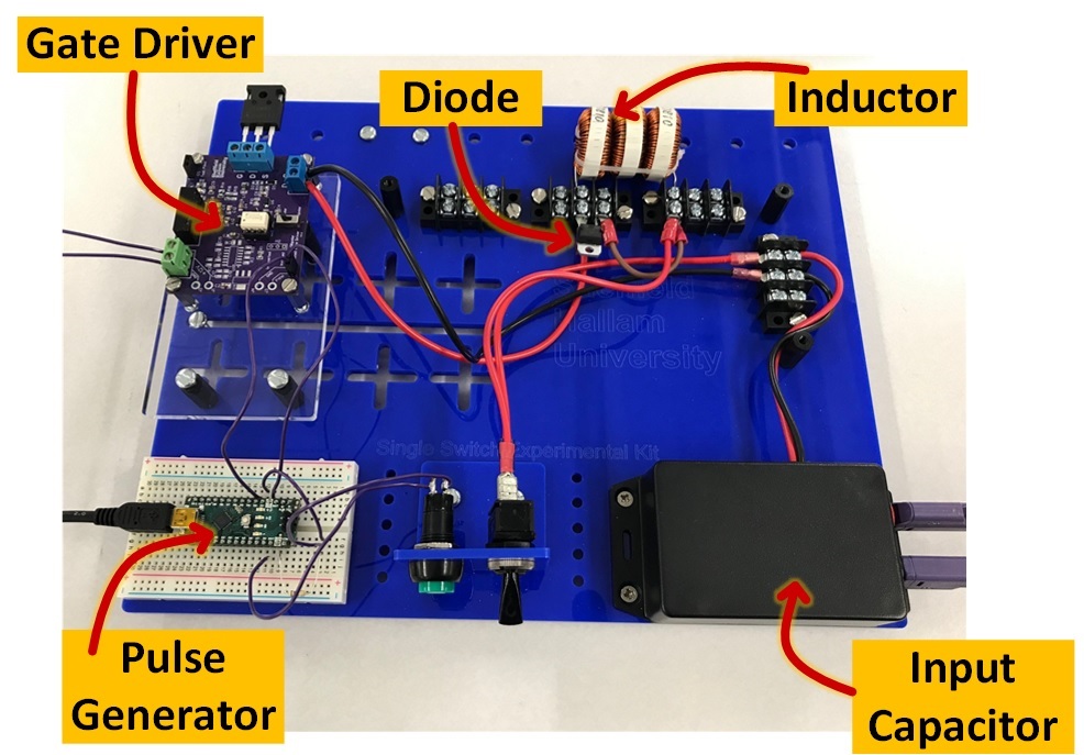
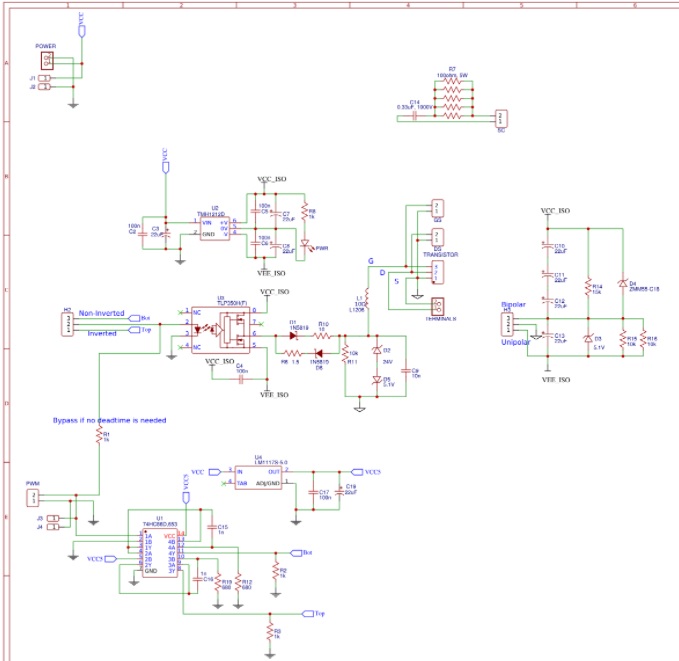
The kit includes a developed gate driver which is able to drive low-side and high-side power switches, and provide unipolar and bipolar switching. It includes an Arduino for signal generation, inductors and capacitors based on the topology.
The photo below shows a manufactured kit at SHU in addition to the developed gate driver.
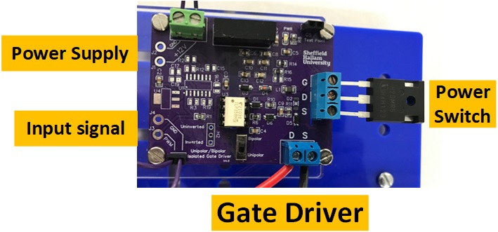
The gate driver schematic is shared online on OSHWLAB site and can be found on this link: https://oshwlab.com/walidissa/bipolar-gate-driver_copy_copy_copy
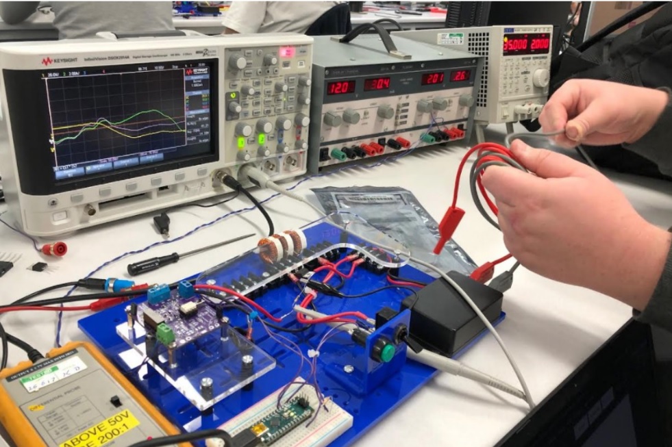
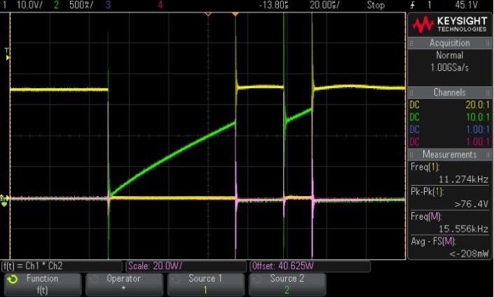
The students started in February to manufacture and assemble the kit to conduct Double Pulse Testing for various power switches. The students work in groups and shared the screenshot of the results. However, the submitted work is based on an individual report.
A sample Arduino code to generate the double pulse test signal is shown below
void setup() {

pinMode(3, OUTPUT);        // Output for Double Pulse
digitalWrite(3, LOW);
pinMode(2, INPUT);        // Input from switch to start the test
}

void loop() {

while (digitalRead(2) == 0) {}

digitalWrite(3, HIGH);

delayMicroseconds(60);       //First Pulse time, change it to suit your current target

digitalWrite(3, LOW);

delayMicroseconds(20);     //Delay between two pulses

digitalWrite(3, HIGH);

delayMicroseconds(10);    //Second Pulse time, change it to the limit where you can capture to on-transisiton properly

digitalWrite(3, LOW);

delay(5000);

}